CLICK HERE to download cable assembly and interconnection information.
RJ-45 cable is used to provide a communication link between two CQ Series products. Once this cable is connected, two CQ Series devices operate in a plug-and-play manner and will turn on and off in the prescribed order.
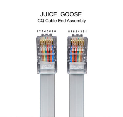
While this cable is the same component used to assemble CAT5 and CAT6 cables, orientation of the connectors on the CQ Series cable is slightly different than for the CAT data networking cable. Therefore, standard CAT5 or CAT6 cables will not work with CQ Series devices.
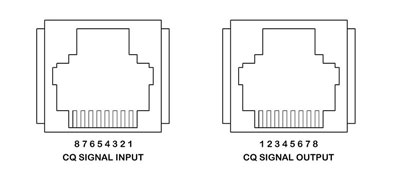
Pin Orientation for CQ Cables
Pin orientation for CQ Cables conforms to standard telephone design, rather than data network design. In this telephone configuration, Pin #1 on one side of the cable is Pin #8 on the other. After crimping a RJ45 connector on one end of the eight wire cable, attach a connector on the other end "upside down" from the first so that when the connectors are placed side by side the wire orientation will appear as shown in the above illustration. Check the cable with a continuity tester prior to installation.
There is no known distance limit for the connection CQ units by means of this cable system. The CQ signal is not sensitive to voltage changes or frequency interference.
Remote Switch Connection
Although a Juice Goose CQ Series product can be remote controlled with a Juice Goose RC-5 accessory or another CQ device, it can also be remote activated with a simple contact closure using a switch or relay. The following instructions are provided to assist with this configuration. This information is also useful for assembling interface wiring going to and from the RJ type cable specified for the CQ system.
In the illustration below, connecting a single pole, double throw (SPDT) switch to the signal input line of a CQ Series device will control the sequence up and down activity. Closing Pin 3 to Pin 7 will begin a sequence UP. Closing Pin 4 to Pin 7 will begin a sequence DOWN. Closing both 3 and 4 to 7 will PAUSE. the sequence process. The control switch on the chassis will be inoperative, except for the Manual On feature, when there is such a contact closure on the input line.
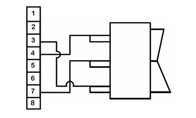
Single Pole
Double Throw
Latching Switch
PIN Assignments
The chart below shows assigned values and functions for each of the eight pins on the RJ45 connectors on the CQ Series Signal Input and Output. Note: although there are eight pins, only the middle six are being used. This information may be used to connect a latching contact (as per the diagram on the previous page), for diagnostics or to design a non-conventional control or monitor component.
Pin assignments are correct when viewed from the outside of the chassis.